Preflight
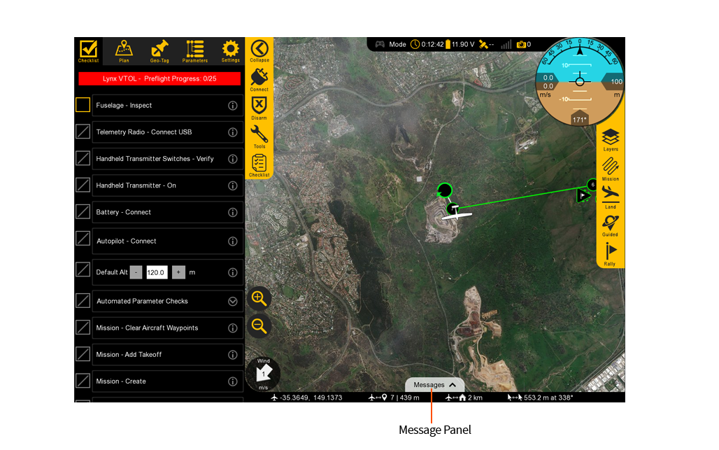
Swift GCS features a built-in preflight checklist for getting Lynx VTOL ready for flight. The built-in steps replace the traditional paper checklist. Some of the steps are automated, while other steps require you to interact with the aircraft or GCS.
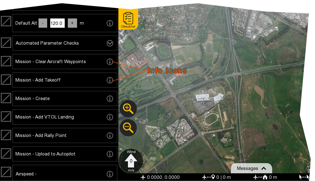
There is an info icon next to each step of the preflight within the GCS. Click on the info icon to reveal additional information pertaining to each step.
Tip: We recommend that you perform your first flight in a large obstacle-free area and limit the length of the mission in order to familiarize yourself with the Lynx VTOL in flight.
Before each flight, you should be aware of the weather conditions. Lynx VTOL is a small drone that cannot fly in heavy rain or strong wind conditions. In case of doubt, make sure to check a weather bulletin including wind estimations in the flight area. Note that wind is often stronger at higher altitudes and that the wind perceived at the surface is not always a good reference to estimate the wind at flight altitude. Cloud velocity or tall tree movements can help you to estimate the wind speed once you are out in the field. Weather forecasts may use various units to measure wind speed.
Warning: Lynx VTOL’s simple design means it can be ready for flight in minutes. You must, however, perform the following preflights steps before every flight to ensure that the aircraft is prepared for flight. Failure to preform a preflight step can result in a crash and loss of the aircraft.
Aircraft - Inspect
Visually inspect the aircraft for damage or wear.
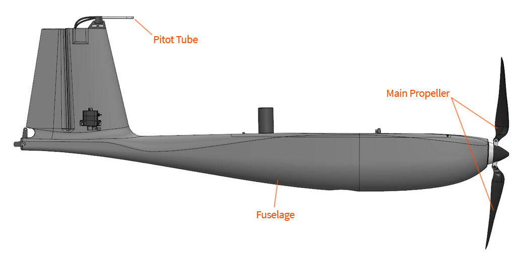
Fuselage: Inspect the fuselage for cracks or other damage.
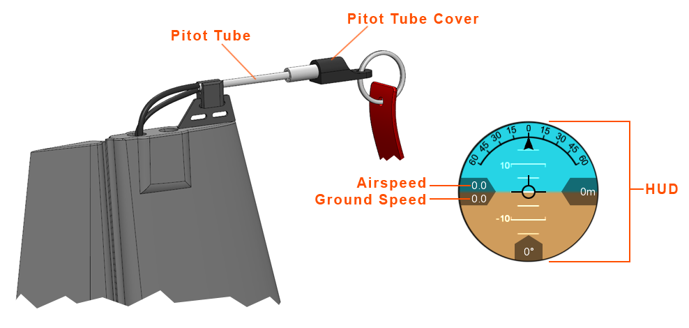
Pitot Tube: Check that the pitot tube is attached to the fuselage and that the tube is free of obstructions. Check the hoses behind the pitot tube for kinks or damage.
Main Propeller: Fold the propeller blades outward after removing the fuselage from the transport case. Inspect the propeller blades for chips or other damage.
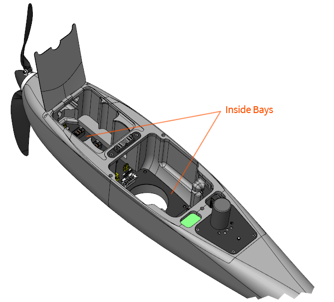
- Inside Bays: Ensure the inside of the fuselage, especially within the battery connectors, is free of dust and debris.
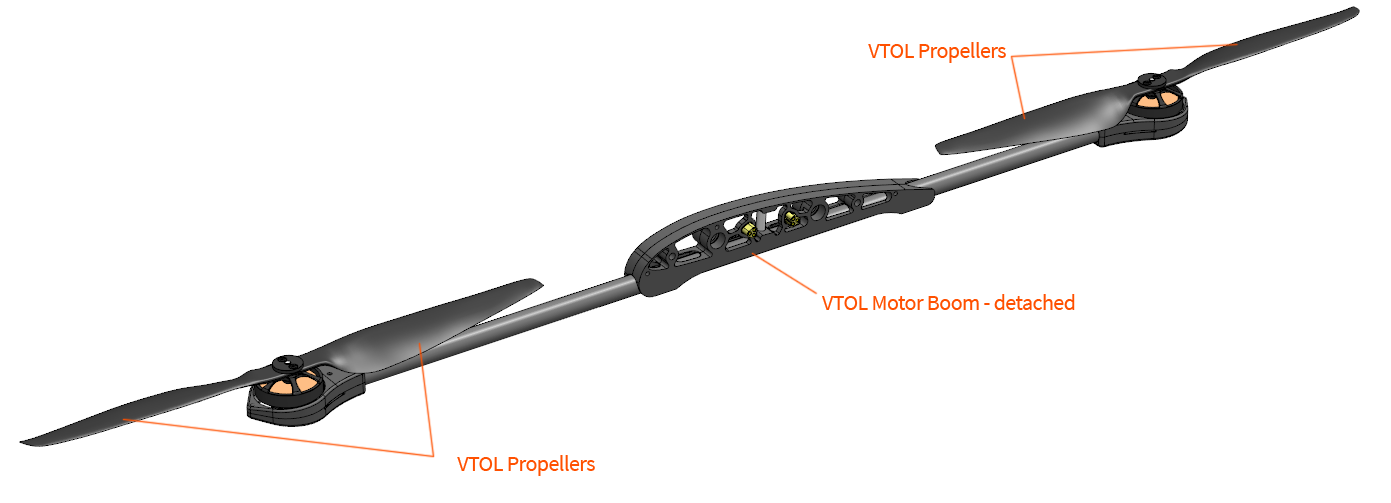
- VTOL Propellers: Inspect the propeller blades for chips or other damage.
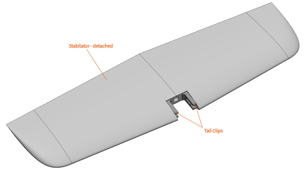
Stabilator: Inspect the stabilator for cracks or other damage.
Tail Clips: Inspect the tail clips for cracks and ensure that they are securely fastened.
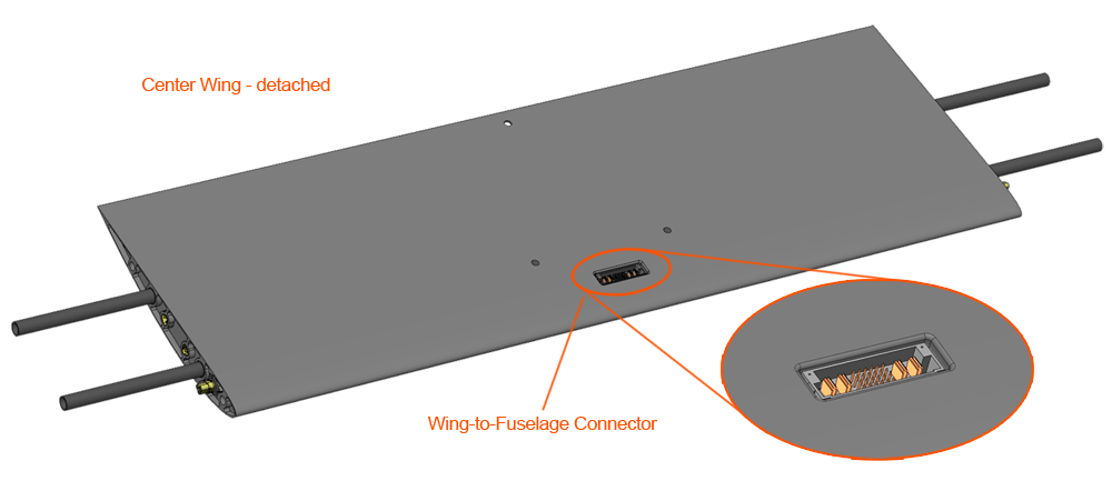
- Center Wing: Inspect the center wing for cracks or other damage. Inspect the wing-to-fuselage connector for bent or damaged pins.
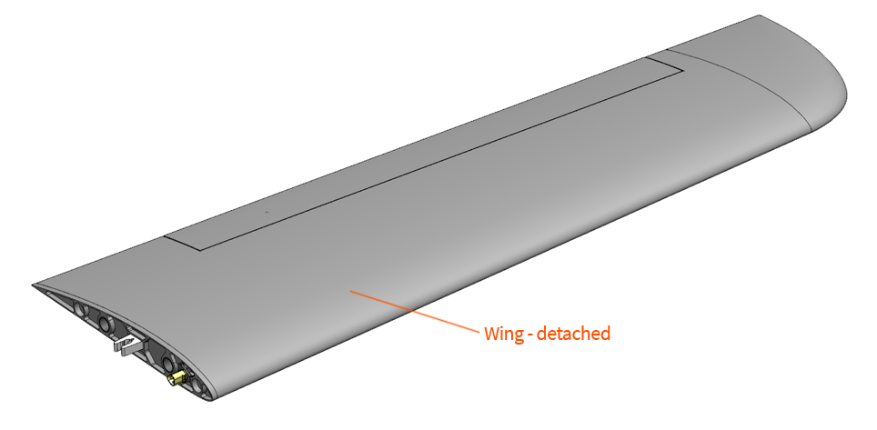
- Wings: Inspect the wings for cracks or other damage.
Telemetry Radio - Connect USB
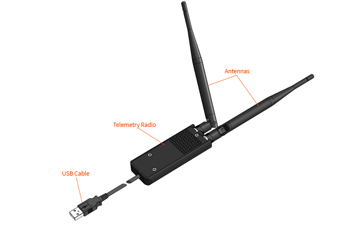
Connect the telemetry radio USB to your GCS computer.
The standard Lynx VTOL telemetry radio frequency uses 915 MHz. The antennas should be spaced apart 90 degrees from each other for best reception.
RC Controller - Verify and Turn On
Verify the RC controller switches are in the correct position and then turn it on.
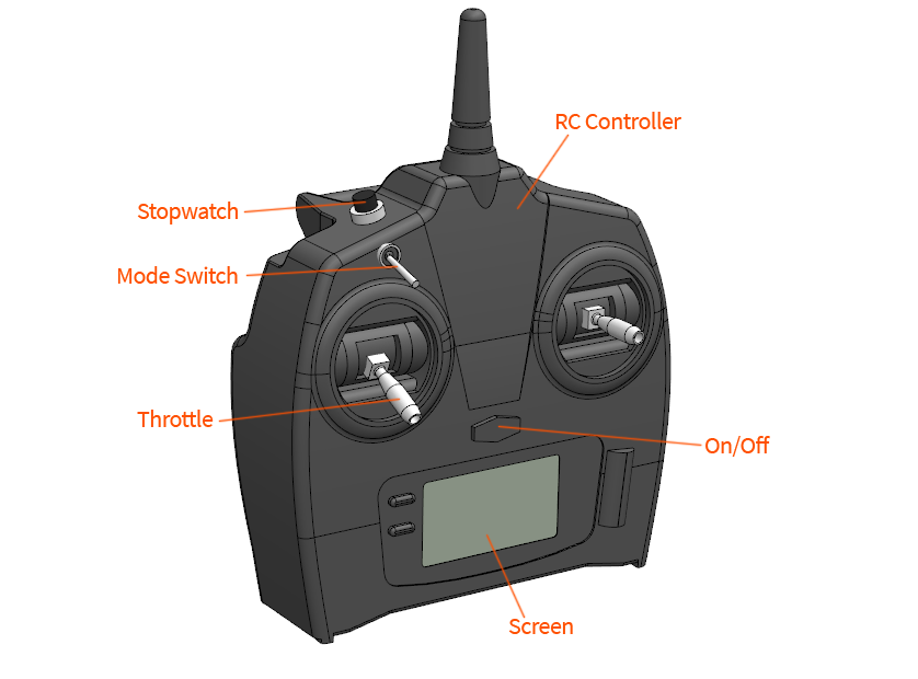
Throttle: Ensure that the left stick is down, into the zero throttle position.
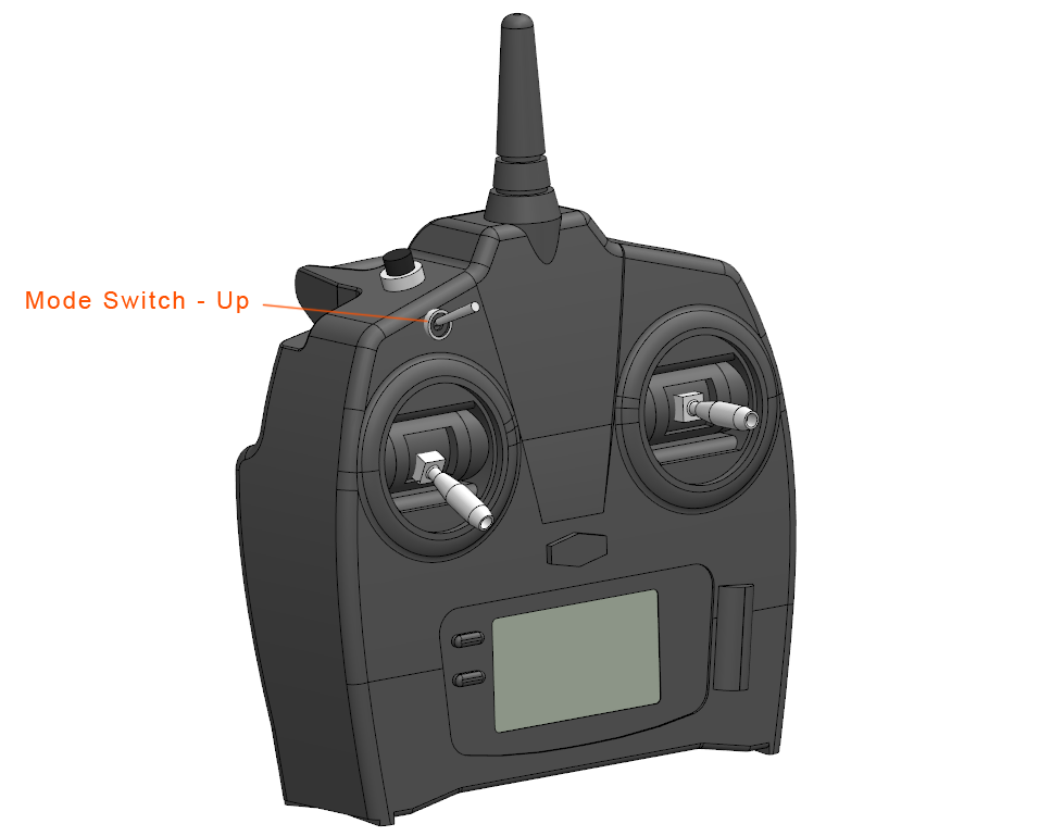
Mode Switch: Ensure that the mode switch is down, into the manual position.
On/Off: Turn the RC controller on after both throttle and the mode switch are in the correct positions.
The position of the other RC switches is inconsequential.
When powered-on, the RC controller’s screen will display the Lynx VTOL tail number, controller’s battery, and stopwatch. Ensure the tail number displayed matches your aircraft, and that the controller is charged.
Battery - Connect
Place the fuselage on flat ground. Insert fully-charged batteries into the battery bay and press downward. The battery is fully seated when you cannot press it down any further. The order in which the batteries are installed does not matter. The aircraft will energize after the second main battery is installed. Once all three batteries are connected, close the hatch.
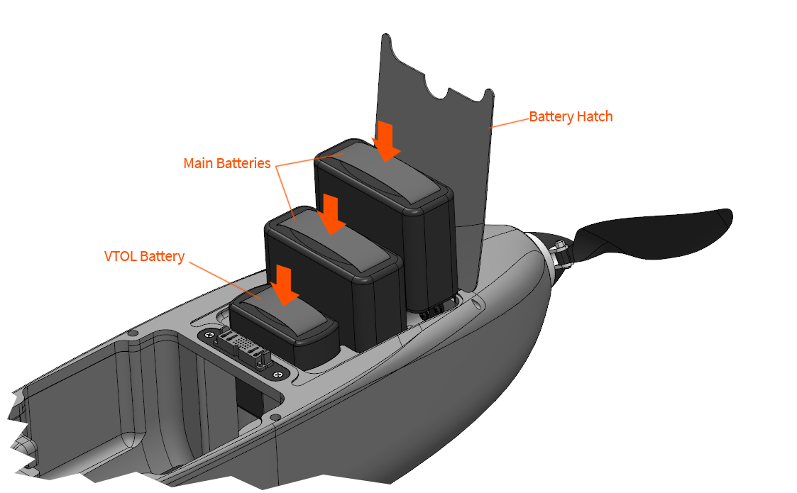
Main Batteries: The two main batteries are connected in series and power the avionics and fixed-wing equipment.
VTOL Battery: The VTOL battery is dedicated to the VTOL motors and is only used during vertical flight modes (such as takeoff and landing).
Warning: The main motor is now energized. Always keep clear of propellers when the aircraft is armed, taking-off, or landing, and whenever possible while the aircraft is powered-on.
Caution: The battery connectors are keyed and only fit one way. Forcing the battery into the wrong orientation may damage the battery, the connector, and/or the aircraft.
Caution: Only connect the batteries when you are ready for start-up. Do not leave the battery connected for extended periods of time when the aircraft is on the ground, as this may discharge the batteries and cause equipment within the fuselage to overheat in direct sunlight.
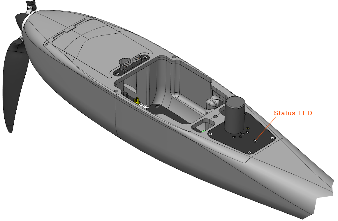
As soon as the aircraft is power-on, the autopilot and its sensors will begin to initialize. Avoid moving the aircraft during these first few seconds. The status LED will blink blue and red. Once initialized, the status LED will change to blinking yellow. See the Status LED Meanings section for more details on the status LED.
Autopilot - Connect
Wait until the telemetry radio's status LED displays solid green/blinking red before proceeding.
Press the Connect button on the Checklist tab and use Auto Detect to automatically detect the correct radio to use.

If bluetooth is enabled, Auto Detect may fail to connect and get stuck trying to wake up remote serial devices. In this case the correct serial port should be selected from the menu.
The GCS will automatically check if a firmware update is available upon connecting. If an update is available the GCS will open a dialog which states that a firmware update is available. Please follow the insturctions in Firmware Update for instructions on how to update the firmware.
Default Altitude - Set
The default altitude sets your mission altitude. The altitude is referenced as a height above ground from where the aircraft takes off from. That location is known as home. Mission items will default to this altitude when planning a flight, except for takeoff and landing transition. Individual mission items can be modified on the Plan Tab if they need to be higher or lower than the default altitude. At this time, Lynx VTOL does not support terrain following.

Choosing the appropriate flight altitude for your mission is critical and dependent upon imagery resolution requirements, ground coverage vs. time, terrain, obstacles, other air traffic, and local regulations.
Caution: Changing the default altitude does not affect any mission items that have already been planned. Items that have already been planned must be individually edited or cleared.
Automated Parameter Checks
The GCS will automatically check that the autopilot parameters are correctly configured.
Caution: If any parameters fail the check please contact support@srp.aero. Do not fly.
Mission - Clear
The existing mission on the aircraft must be cleared before a new flight.
Do this from the Plan Tab by selecting Clear ⇨ Clear mission on the aircraft.
In order to clear a mission on the aircraft, the aircraft must not be in the Auto mode.
Mission - Add Takeoff
From the Plan tab, select Add ⇨ Takeoff to insert a takeoff at the start of the mission. The default takeoff altitude is 30 meters above home. The aircraft will climb vertically to this altitude and then transition to forward flight and proceed to the remainder of the mission, climbing enroute as needed. The takeoff direction, or heading, is determined by the wind. The aircraft will automatically weathervane to face the wind during the vertical climb and transition.

Caution: If flying with a GCS other than Swift GCS, please see Flying with an different GCS. Failure to plan the takeoff correctly can result in failsafes not working correctly and may result in a crash.
Mission - Create
Create or load a mission from the Plan Tab.
Refer to the Mission Planning section for help with creating a survey grid.
Mission - Add Landing
From the Plan tab, select Add ⇨ Landing to insert an autonomous landing into the mission.
The default transition altitude is 30 meters above home.
There are several ways to plan where the aircraft lands. The location can be selected by clicking on the map, by using the aircraft’s position (this option is only available during the preflight), or by using a computer that has a built-in GPS. Using the aircraft’s position will result in the best landing accuracy.
You will see your landing waypoint on the map with a dashed line around it. The dashed line represents the radius of the landing pattern. It is important to keep this radius away from obstacles that are near or higher than your transition altitude when planning the location.
The landing pattern is automatically generated. The heading is affected by the wind direction. Similar to a takeoff, the aircraft will fly into a headwind for the transition and weathervane during the vertical descent.
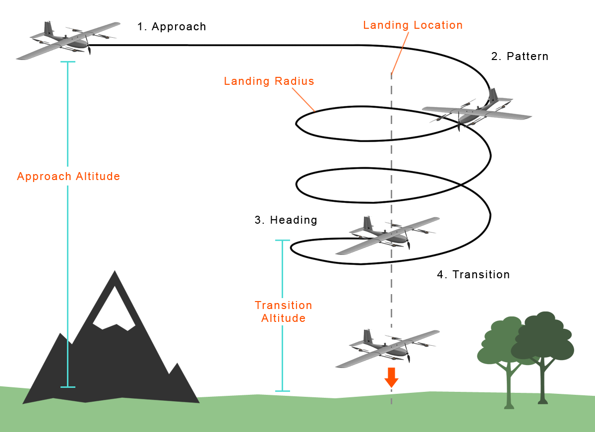
The pattern is divided into four distinct phases: 1. Approach, 2. Pattern, 3. Heading, 4. Transition
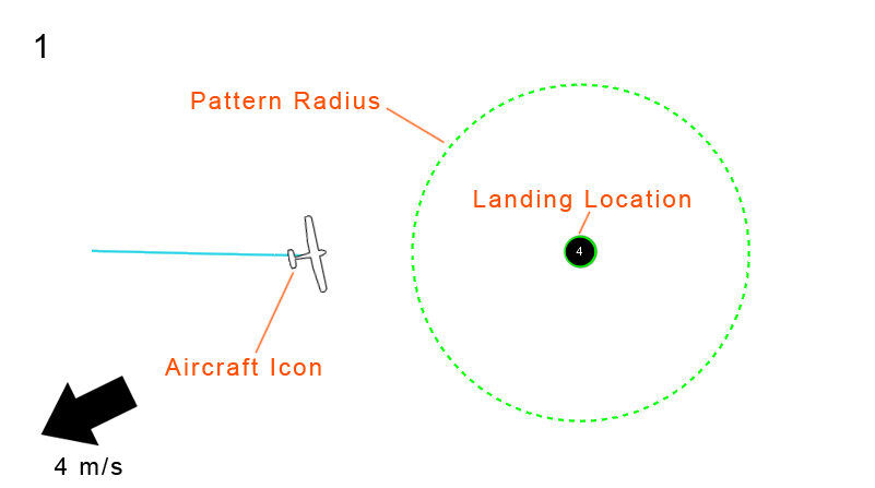
Approach: In the approach stage, the aircraft will fly to the landing location from its previous waypoint. The altitude of this approach leg will be the same as your default altitude unless you have configured the landing differently from the Plan Tab. If your previous waypoint was lower than the approach altitude, the aircraft will climb during the approach and vice versa. This must be considered with regards to terrain and obstacles.
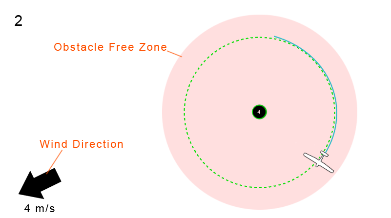
Pattern: Once near the landing location, the aircraft will enter a 150 meter radius circle and descend to the planned transition altitude. The default transition altitude is 30 meters. The area within the landing circle must be free of obstacles near or above the transition altitude.
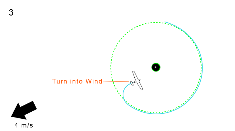
Heading: Upon reaching the transition altitude, the aircraft will pick a heading that is into the wind. Once the path has been selected, the aircraft will turn into the wind and fly towards the landing location.
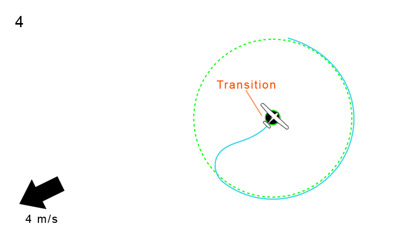
Transition: The aircraft will automatically transition from forward flight into a hover just before the landing location. Lynx VTOL will then descend vertically over the landing spot. Upon reaching the ground, the aircraft will automatically disarm and stop spinning the motors after a short delay.
Landing procedure, seen from the side.
Caution: With an autonomous landing, the GCS operator has no direct input on the landing once the aircraft has transitioned.
Caution: If flying with a GCS other than Swift GCS, please see Flying with an different GCS. Failure to plan the landing correctly can result in failsafes not working correctly and may result in a crash.
Mission - Add Rally Point
From the Plan tab, select Add ⇨ Rally to insert rally points into the mission. Multiple rally points can be added.
Rally points are used to control where the aircraft will go in the event of certain failsafes. When the aircraft wants to fly to a rally point, it will select the nearest one. The aircraft will circle around this point until the operator changes the flight mode, or a more critical failsafe activates.
Rally points should be planned in safe locations, free of obstacles, and within radio range of the operator. Multiple rally points can be staggered throughout an area for large missions, especially if the operator is mobile.
For more information about rally points please see the section describing the rally mode.
Caution: If there are no rally points within 5 kilometers of the aircraft during a failsafe or if you choose the flight mode rally, the aircraft will fly to home and circle, descending enroute to an altitude of 100 meters.
Mission - Upload to Autopilot
From the Plan tab, select Upload. This will upload the entire mission to the autopilot.
Autopilot Warmup - Wait
The autopilot has an internal heater to hold the IMU at a specific temperature which improves the accuracy of the sensors. Please wait for the IMU to reach the required temperature before proceeding.
Airspeed - Calibrate
This step will walk you through calibrating your airspeed sensor.
First shield the pitot tube from any wind with the provided pitot tube cover.
Next, press the Calibrate button on the Checklist Tab.
Remove the pitot tube cover to test the airspeed sensor.
To test, tap and hold the tip of the pitot tube with your fingertip while watching the airspeed reading on the Heads-Up Display (HUD).
The reading should exceed 6 m/s. If you cannot exceed 6 m/s, gently blow into the front opening of the pitot tube from a distance of around 5 cm.
At rest, the displayed airspeed should be close to zero, but it may drift up to 2 m/s.
Payload - Check
Check that your payload is configured correctly. See the Payload section here for more information.
Lynx VTOL may be flown safely without any payload.
The max payload weight is 500 grams.
Camera - Synchronize
The sync step is only required if doing a photomapping mission. If no survey grid was planned, then the step will automatically be shown as complete.
This sync process is not required if doing a PPK flight, however it is still recommended, as it provides a fallback geotagging option.
This step is used to check that the camera triggering circuit is working, and to create a marker in the autopilot log that is used for tagging.
Step 1: Press the Sync button to begin the process.
Step 2: The GCS will prompt you to ensure that the camera is installed and connected to the aircraft. Press Yes button to proceed.
Step 3: The GCS will prompt the aircraft to take a photo, at which point you should hear the camera trigger. If a photo was taken then select Yes button to continue. If no photo, select No and double check the connection to the camera, the camera settings, camera storage, and camera power.
Step 4: You are now ready to take the sync photo. This is a photo you will need to find during the geotagging process, so ensure that the camera is pointing at an object you can recognize later. When ready, press the Take sync photo button.
Tip: Taking a photo of your hand or shoe is fairly easy to do and makes a distinctive photo for the tagging process.
Step 5: Select Yes to continue if the sync photo was successfully taken. If this failed then there is something unreliable with the connection to the camera, and you should inspect all the connections and settings before restarting the process.
Aircraft - Assemble
This step will walk you through assembling your Lynx VTOL

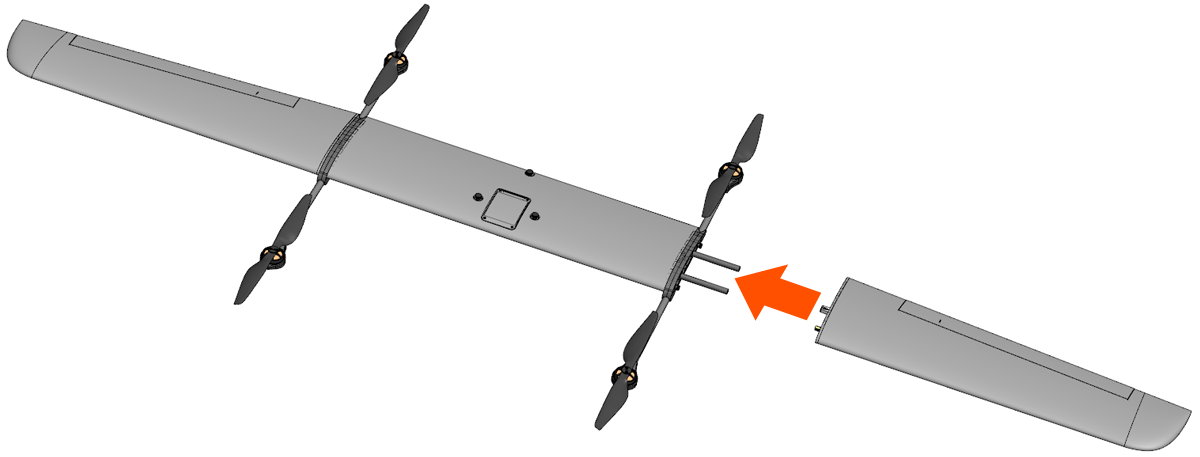
Step 1: Attach one of the motor booms to the center wing by sliding it against the spar joiners. Loosen the motor boom thumbscrews such that they do not stick out on the side facing the center wing. Keep sliding the motor boom against the center wing until flush. The motor connectors should now be fully seated.
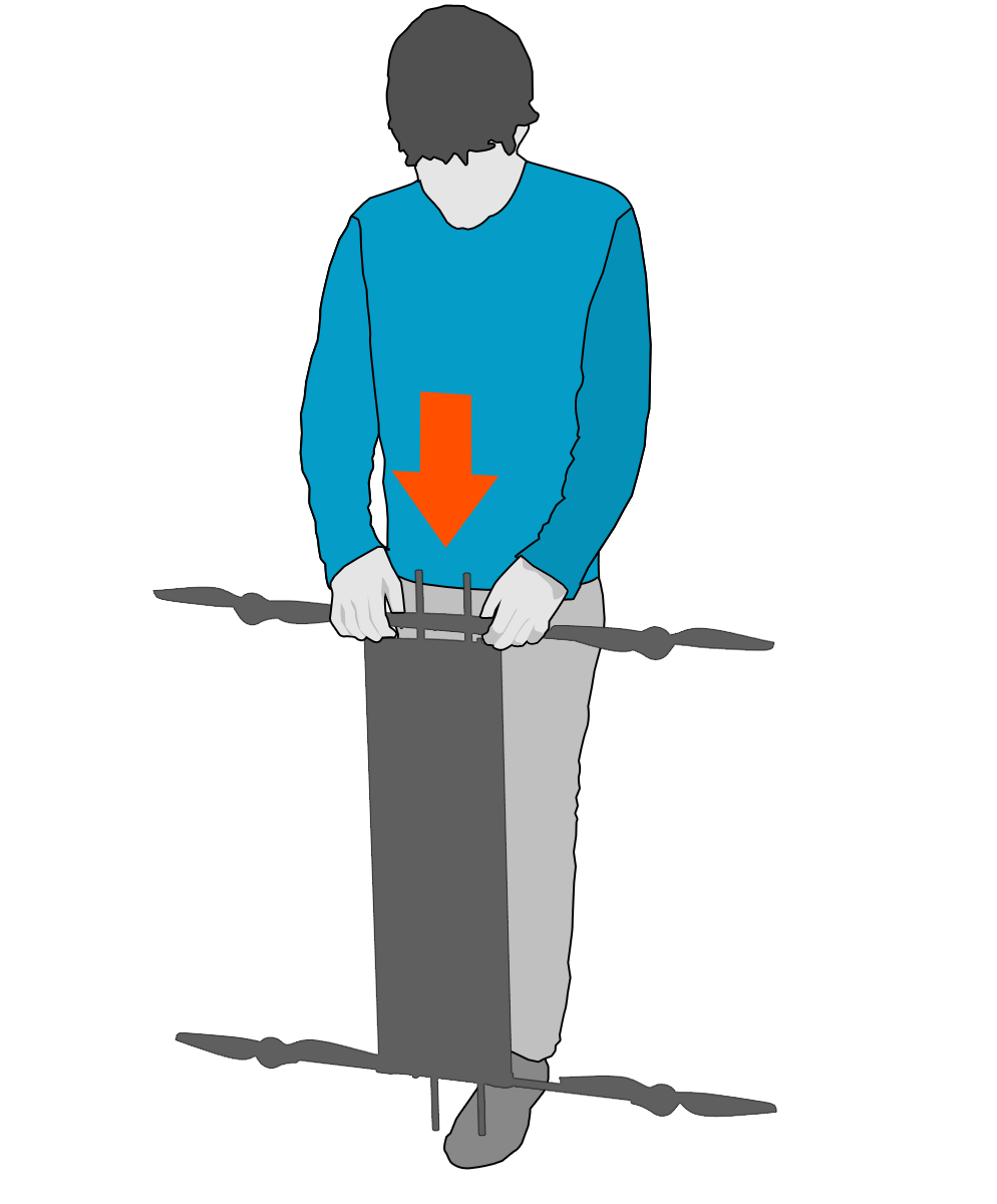
Tip: Place one end of the center wing against your shoe such that the wing is standing vertically. Align the motor boom with the spar joiner and press down.
Caution: Do not force the motor boom if the connectors do not align. Instead, wiggle the motor boom until the connectors align.
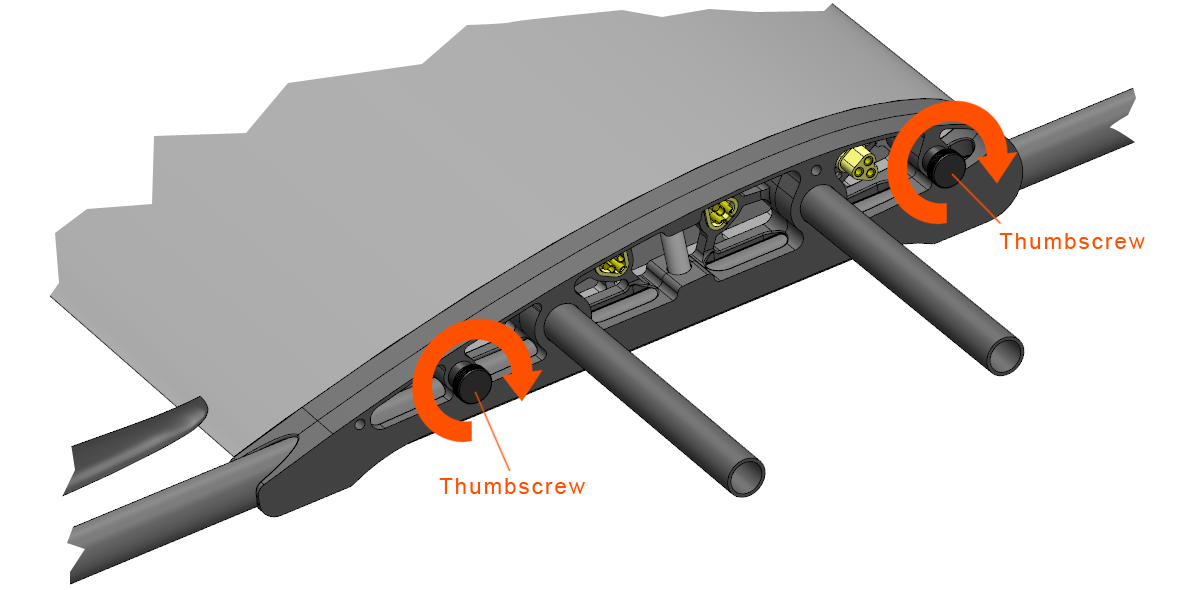
Step 2: Tighten the 2x motor boom thumbscrews to secure it against the center wing.
Step 3: Attach the other motor boom using the same process.
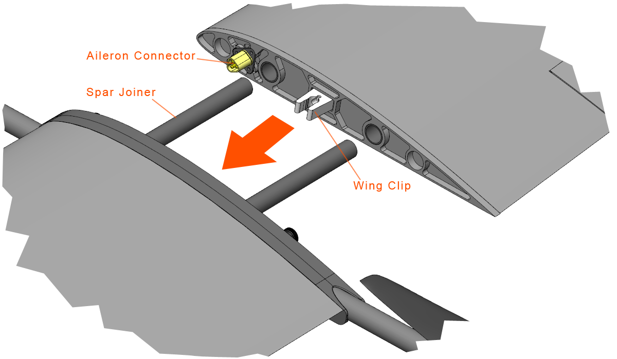
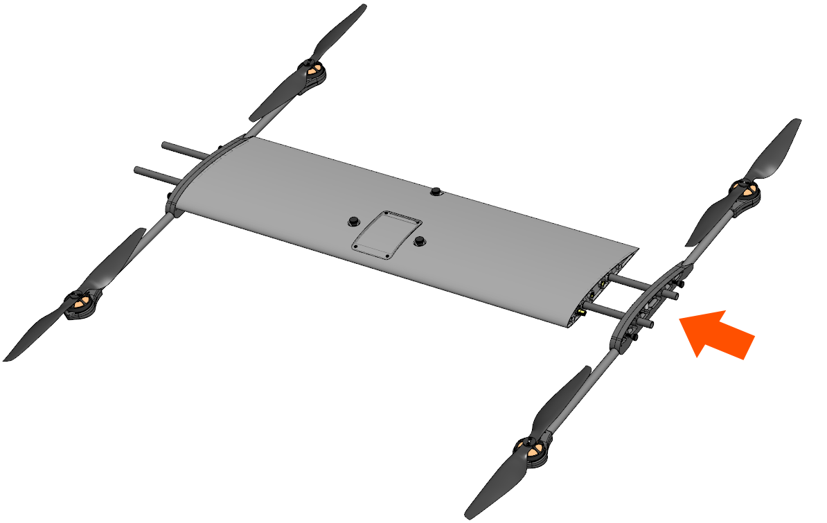
Step 4: Attach one of the wings to the center wing by sliding it against the spar joiners. Keep sliding the wing against the center wing until the wing clip engages. The wing should now be nearly flush with the motor boom.
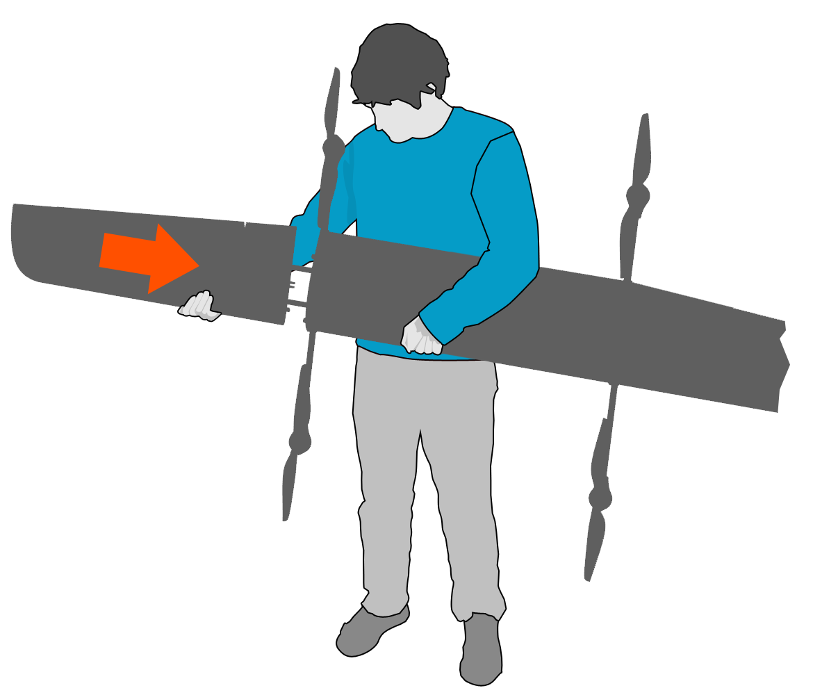
Hold the center wing horizontally and flat against your stomach. Point the leading edge (front) of the wing down. Holding the center wing with one hand, and grasp the leading edge of a wing with your other hand. Line-up the spar joiners and slide the wing together.
Caution: Do not force the wing if the aileron connectors do not align. Instead, wiggle the wing until the connectors align.
Step 5: Attach the other wing using the same process.
Step 6: Ensure the battery hatch is closed and flush with top of the fuselage.
Caution: If the battery hatch is not properly aligned with the fuselage, it may interfere with mating the fuselage-to-wing connector.
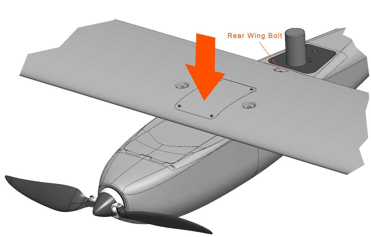
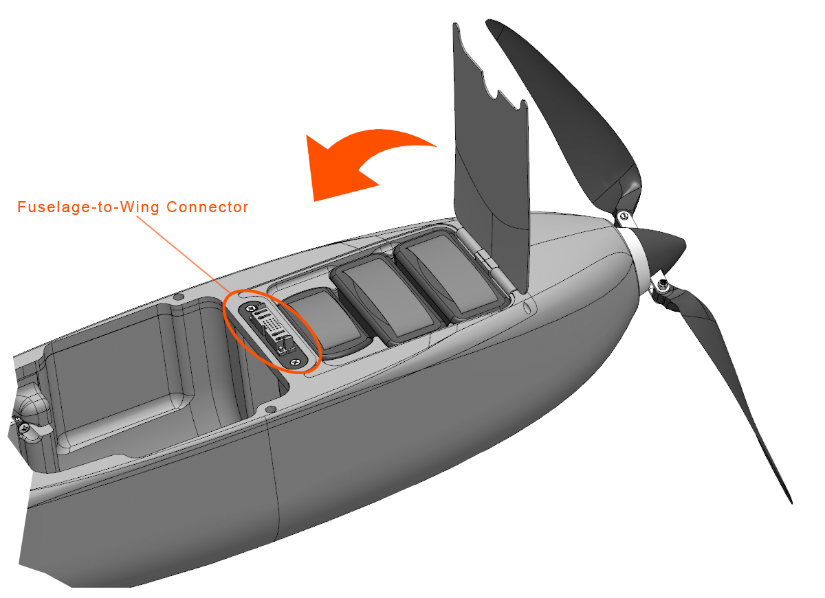
Step 7: Attach the entire wing to the fuselage. Place the wing atop the fuselage. The wing should be centered and aligned with the fuselage-to-wing connector. Use the rear wing bolt slot to visually center the wing and align it to the bolt threads. Once aligned, gently press down on the wing until the fuselage-to-wing connector is fully seated. The VTOL motors will audibly beep when the connector is seated.
Caution: Do not force the wing downward onto the fuselage if the connector does not align. Doing so may damage the connector’s electrical contacts.
Warning: The VTOL motors are now energized. Always keep clear of propellers when the aircraft is armed, taking-off, or landing, and whenever possible while the aircraft is powered-on.
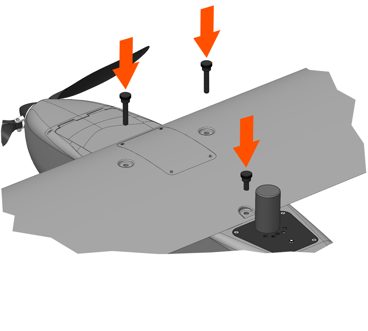
Step 8: Secure the wing to the fuselage by inserting and finger-tightening the wing thumbscrews.
There are three wing thumbscrews. The two in the front are longer than the rear one.
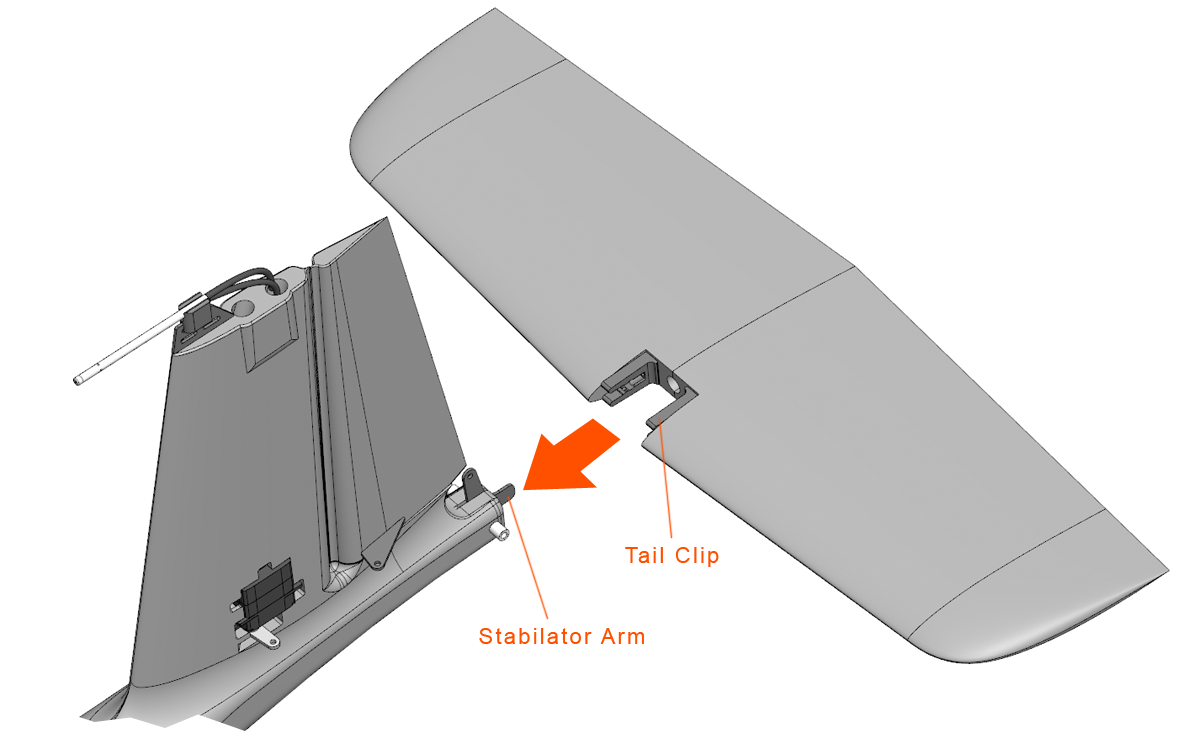
Step 9: Attach the stabilator to the fuselage by lining up the stabilator arm and tail clips. Press the stabilator against the fuselage until it clips into place.
Compass - Check
Check that the compass is behaving correctly by pointing the aircraft at a known object and then verify that the map shows the aircraft pointed at the same object. Rotate the aircraft in 90 degree increments and check that the map and aircraft continue to agree. No warnings should be triggered while performing this check.
Caution: If the heading is off from where the aircraft is actually pointing by 10 degrees or more, you may need to perform a compass calibration. Please see the calibration section for more information.
Changing the aircrafts payload may change the required compass calibration. Please see the calibration section for more information.
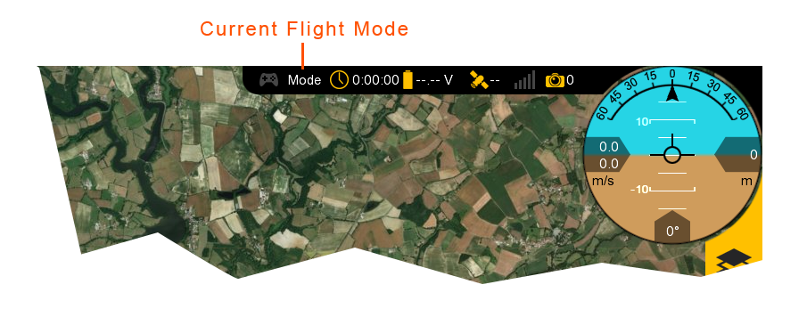
Mode - Auto
Using the RC controller, change the current flight mode to auto by moving the mode switch all the way up. Swift GCS will display the current flight mode at the top.
Initial Waypoint - Set
This step verifies that the initial mission item is set to a takeoff.
Control Surfaces - Enable
This enables the aileron, rudder, and stabilator flight control surfaces to move.
Throttle will still be disabled.
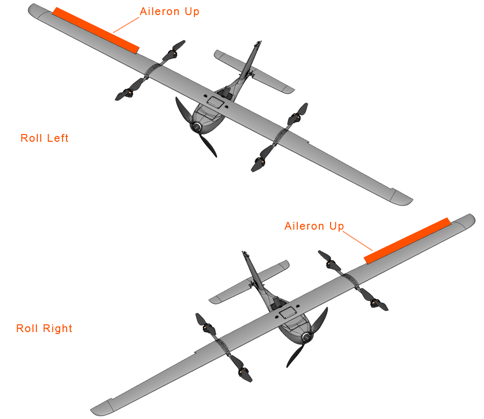
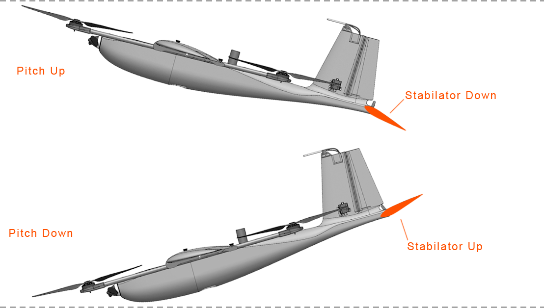
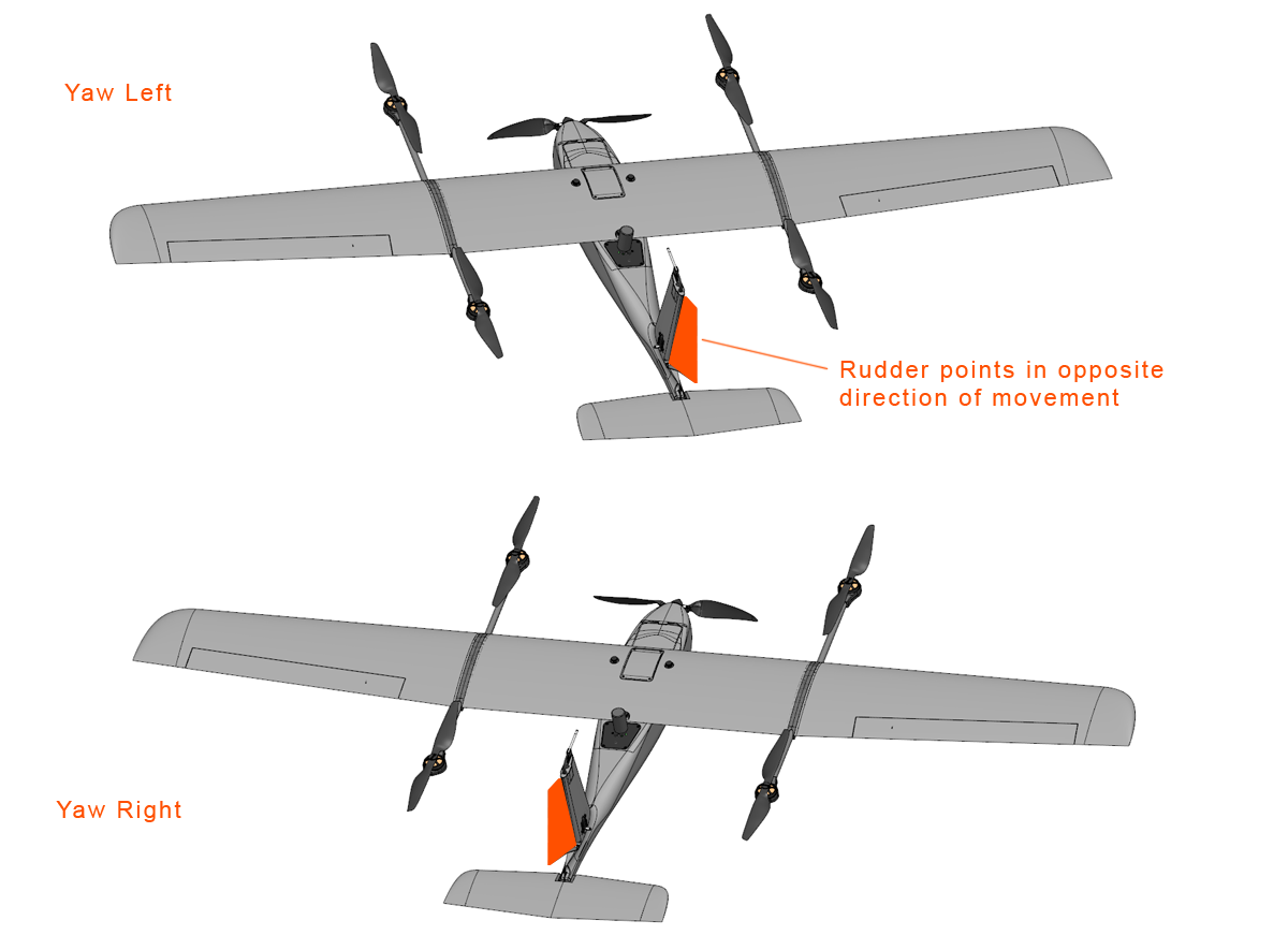
Control Surfaces - Check
Move the aircraft to test that the autopilot is responding correctly to attitude upsets. Do this by observing how the flight control surfaces react to rotations in all three axes: pitch, roll, and yaw (heading). The control surfaces should oppose the movement in each direction. For example, when the aircraft is rolled, the ailerons should be trying to return the aircraft to level.
No Warnings - Verify
Ensure that there are no warnings before takeoff. All warnings must be resolved.
Takeoff - Ready?
Double check the wind direction and velocity. Do not takeoff if the wind speed exceeds the Lynx VTOL system limitation of 10 m/s. Ensure that the aircraft is pointing into the wind. The takeoff area should be clear of bystanders and obstacles. Notify everyone participating in the flight that the aircraft is about to takeoff.
Aircraft - Takeoff
This step arms the aircraft and then immediately commands a takeoff. Lynx VTOL will spin the VTOL motors and climb vertically to your takeoff altitude, by default 30 meters. During the ascent, Lynx VTOL will try point its nose into the wind, or weathervane, to assist the takeoff. Upon reaching your takeoff altitude, the aircraft will transition to forward flight and climb enroute to the next item in your mission.
Caution: The operator has no direct input on takeoff once the aircraft has been armed. However, there are a number a situations that will cause the autopilot to automatically abort the takeoff.
Warning: Arming the aircraft allows the autopilot to spin propellers.
Arming finalizes your home location.
The aircraft must pass a series of automated pre-arm checks before arming is finalized. Failed pre-arm checks will be displayed in the warnings panel.
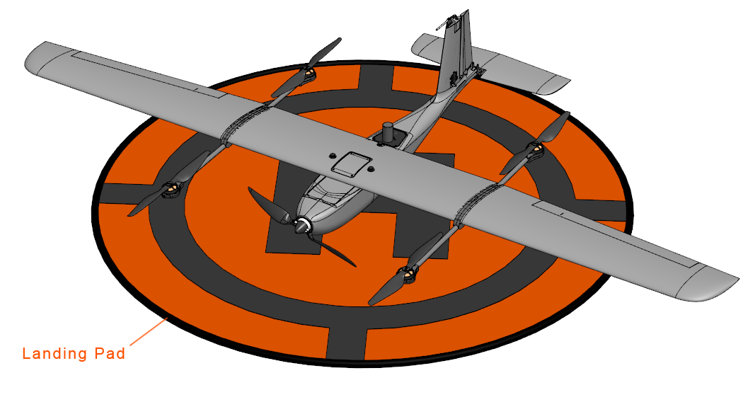
The thrust generated by the VTOL propellers on takeoff and landing can kick-up dust and loose debris. Use a landing pad or similar to reduce the amount of dust when flying from dusty environments.