Mission Planning
Survey
To create a mapping mission, a survey grid will need to be created in Swift GCS.
Select the Survey button from the Plan tab to add one.
You will be prompted to load a KML (or KMZ) file or to draw a new area by placing polygon points on the map.
Polygons that you create in Swift GCS can be saved for future use.
The survey grid makes all calculations based off the camera you selected from the list.
Adjusting the flight altitude will allow you to change the ground sampling distance (GSD), or simply put, the imagery resolution.
Reaching the start of a survey will cause the camera to begin taking photos. The camera will continue to take photos until the last waypoint in the survey is reached. If you need to land before a survey is complete, the camera will continue taking photos until on the ground. This is fine, but those photos may need to be deleted before processing.
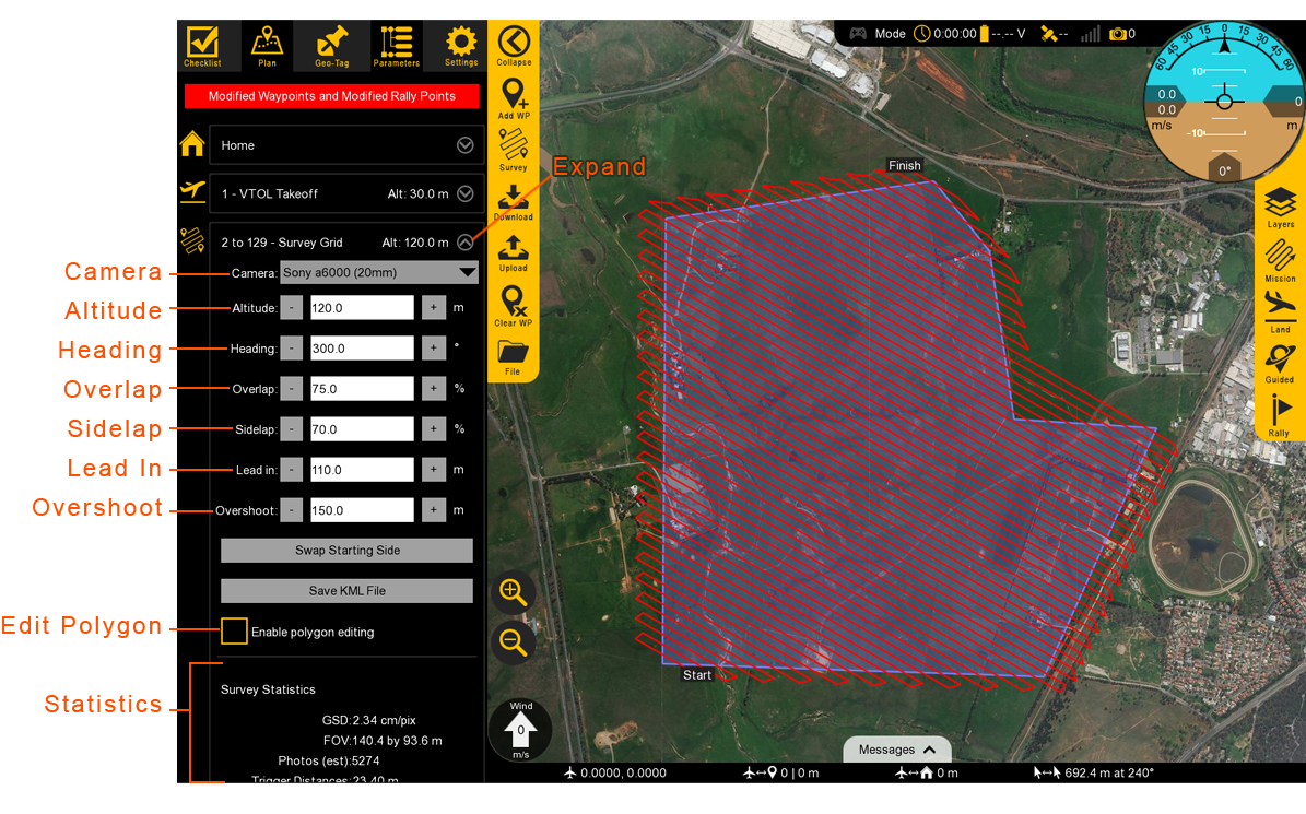
Settings for the survey mission can be modified by expanding the survey item in the list of mission items.
Camera
Expand to reveal the list of existing camera profiles. A custom camera profile can be added by going to the Settings Tab, then Camera.
Altitude
Altitude should be set based on the resolution requirements for your mission. It is critical to also account for safety factors such as surrounding terrain, air traffic, and local regulations. Flying higher will always increase your ground coverage vs. time but at the expense of reduced resolution.
Heading
Adjusting the heading control the direction of the flight legs. Flight legs should be perpendicular to the prevailing wind (crosswind). This will cause the aircraft to crab in flight but will result in a consistent ground speed from one flight leg to the next. A headwind/downwind scenario will cause the aircraft to have a slow ground speed one direction, and a high ground speed in the other direction. A high ground speed may cause motion blur in the imagery. Additionally, if the ground speed is high enough, the camera will be unable to take photos quickly enough which will result in missing photos.
You will be able to choose what side of the polygon the aircraft starts at with the Swap Start button. When possible
, choose the starting position that will cause the aircraft to turn upwind.
The result will be tighter turns between flight legs.
Overlap and Sidelap
Adjusting the overlap and sidelap percentages will control the number of photos that contribute to your mosaic for a given spot on the ground. Overlap controls the distance between photos along a flight leg. Sidelap controls the distance between photos from one leg to the next. The default numbers are 75% overlap and 70% sidelap. The starting numbers should be kept if you are uncertain of the settings, or if you are flying over hilly or forested areas. In areas of flat terrain, it is possible to safely lower these numbers. Doing so will allow you to cover more ground and reduce the amount of data to process. Never reduce the percentages below the minimum required for your imagery processing software.
Lead In and Overshoot
Lead in and overshoot are utilized to make sure that the aircraft is turning around outside the area of interest being mapped. The default values of 110 meters lead in and 150 meters overshoot are suitable for Lynx in most cases.
Statistics
Survey statistics will display information about your survey and polygon. The field of view (FOV) is the cameras footprint at the survey mission altitude. The photo estimation is the number of photos you can expect the camera to take during the survey; that number should be below what the camera’s SD card can store. Lines is the number of flight legs. Distance is linear distance of each flight leg, excluding turns. Time is the estimated duration to complete the survey. Note that the time estimate is based on a zero wind situation. High winds increase the time required to complete a mission because the aircraft’s ground speed is reduced overall. Area is the polygon’s area in square kilometers.
Editing a Polygon
To edit an existing polygon, select Enable polygon editing from within the survey grid item. The polygon corners will now show up as draggable points. Click to add an additional point, right-click to delete a point (tap and hold on touchscreen).
Modifying your Mission in Flight
You can upload a new mission while in flight, but doing so will not interrupt the current destination waypoint. Only the next waypoints will be affected by the new mission or if you restart the mission. For example, if you are flying to waypoint 4, and upload a new mission with 10 waypoints, the aircraft will continue to fly to the original waypoint 4 location and then travel to the new waypoint 5.